Thursday, 17 June 2010

Phase (4)

I was kinda of hoping to write more details in phase (3) before moving on to (4), but let's wrap it here and move to the next phase...

Phase (4)

Integrating.......

This phase defiantly bring memories!

Anyways,

Naturally, the whole team was involved in this phase and we started to assemble the whole thing together. Adding the control part to the mechanical was not a piece of cake at ALL!

we had MAJOR problems...


  • we didn't know how to connect the linear motor
  • the printed circuit was not tested
  • we only had one shot!
  • the program was not tested


and the very best part :D, the motor driver chip exploded with the very first try (I mean we could actually see flame coming out!)

Which didn't exactly give us much of a choice but to re-implement the circuit on a breadboard, which we didn't do. we tried to test the rest of the circuit and add an external chip and connect it.

What we didn't know back then was that the printed circuit already had a problem with the ground/VCC connections and was solved by making a separated vcc/ground connection to a part of the circuit, which people forgot to mention earlier !!!

Oh, and that was just 2 or 3 days before delivering the project :)

problems,stress,deadline........These are the times u learn in the most, not only about the project, but about yourself and the surrounding people!

I am being drifted off point here

tell you what happened next in the upcoming post isA :)

stay tuned ;)
Tuesday, 23 February 2010

Continue Phase (3)....control


Back to the Control Team....

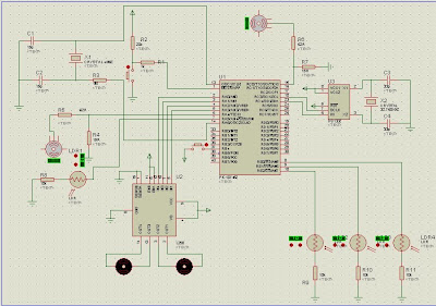
we basically used a microcontroller, the inputs were; sensors and RTC chip. The output was to the motor driver and from it to the two motors.
we searched online for the appropriate interface circuits with the addition to a switch and that was the output.

I wasn't deeply involved at this particular phase really,  but this is how I perceived it...  


Saturday, 6 February 2010

Continue Phase (3)....mechanical design


The pictures as promised in the last post...


those were the first parts we made :)


 That one was at 3ezbet el na7'l, at the workshop where we assembled the parts for the first time :)

This is actually one of the happy moments; when you see what you draw and thought about became reality !!!


Some close up looks...


Rack-Pinion arrangement;
 transferring motion from the linear actuator to the tracker (linear to rotational) 


One of the major difficulties that we encountered during the assembly phase of the tracker was that the non-availability of the type of the rotational encoder we planned to use (disk), we had to use another type and the design wasn't made for this one! so we had to improvise. 

Trial one


Someone in a different team suggested that design for us. Unfortunately it didn't work as the encoder will not exactly rotate with the same angle as the bearing which is VERY not acceptable as the encoder job IS to measure the angle of the bearing movement :S 


Trial two


After several trial and errors, we came up with this design, which is far more accurate and it worked just fine thanks to Allah :)


Final look


That's the final design, after it was polished and the dummy load (glass sheet) was fixed to replace the cells.

Tuesday, 2 February 2010

Continue Phase 3....

The Mechanical Team

Implementing the tracker on real life was a bit different than on papers. It was our first time to actually do something for real!. The amount of knowledge we gained was GREAT but the task was tiring.

Difficulties:
_________
  1. When you drew on inventor a working drawing that says a part should be 32 mm it's easy, but when you tell someone to cut it 32 mm that's another story :D. We had to adjust most of the measurements we had to make it easier to implement
  2. The names you study for things in college whether it's the English term or even the Arabic one is so not what workmen use. For example, what we would normally call a ball bearing with it's seating; is commonly known as "balya wesh 2ora!!!!"
  3. You could make the best design in the world, but when you go do it someone might tell you it's not doable, and they could be very wrong, but if you insisted you could have it your way which is good or the workman might simply tell you "Fine, it's doable but I don't know how to do it!". WHY?? cause they have other stuff to do (mass production) and can't careless about your once in a life time small piece. so you may have to readjust your design for no apparent reason :S (Though I'll have to say that a good group in communicating with workmen would easily get pass this obstacle isA :) )
  4. Rest of obstacles are comfort wise :D (bad place, weired people, horrible weather, no place to park if you had a car, and no transportation if you don't , no bathrooms, barely mosques to pray......yet, I had fun :D:D )

I will spare you the details of the journey and wrap it up with pics  :)
Stay tuned for the next post isA ;)